Electrical Routing & Wire Harness Creation
One of the favorite parts of my job is visiting our customers and finding out how we have helped them, or better still, finding out what we can do to help them even more.
This post is about observing a real world customer problem and solving it: Electrical Routing & Wire Harness Creation.
 Accurate Assembly Instructions for the Shop Floor for Mechanical Parts
Many of our customers assemble machines with a lot of parts, so the use of 3D Work Instructions is a great help for the team that has to learn the assembly process. This is particularly useful when each machine being assembled is different than the last. Handling custom designs or designs with multiple variations and short production runs is a challenge, especially when trying to keep a workforce up to date and trained in each machine they need to assemble.
Whether providing animated instructions via a PC or tablet or providing print-based instructions (created automatically from 3D data), workforces typically benefit from faster training, less scrap or rework and usually getting the instructions and documentation created sooner in the product lifecycle.
Electrical Routing and Harnesses Missing
However, when visiting a customer assembling buses a while ago, I noticed that while the mechanical assembly team had great documentation, the specialists taking care of the wire harness creation and installation did not. They were working with traditional schematics and had very little other documentation to support the creation and installation of the harness. Although there are electrical tools that are used in the design phase, it seems that the data does not transfer well to the assembly, maintenance and service documentation.
The difficulty in handling the wire harness and the challenges posed by not being able to easily include them in created documents led us to rethink our approach. We realized that trying to reuse only the mechanical CAD data was not enough. We needed to provide the ability to easily create realistic electrical routing components.
Integration of Mechanical and Electrical
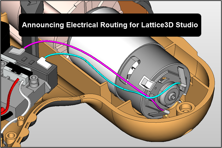
The latest version of Lattice3D Studio – v13.1 – includes a new option to create electrical cables/wires and harnesses within our authoring environment. Now you can easily create wires and cables by specifying start points, end points, and pass through points with a minimum bend radius. You can also easily merge and bundle existing wires and cables to create the harness for documentation. In addition, you can create “smart” connections of wires and cables to mechanical components. The connections are considered “smart” because when moving a part, the wires and cables connected to them are automatically reconfigured. Finally, the length of each wire and cable is automatically calculated – essential information for manufacturing.
The harness and connection information is stored with the same ultra-lightweight 3D model that all other work instruction information (MBOM, Process List, Service BOM, etc.) is stored with.
Conclusion
Technical Communications is our business. Our company’s mission is to leverage 3D CAD models across an organization for any purpose that needs mechanical representation. Handling the wire harness in a way that can easily be included in the documents (2D and interactive 3D) has led us to rethink our approach of only reusing existing CAD data.
By including the electrical routing and harnesses with the mechanical components, a complete representation is realized. This complete representation can be used in animated instructions, technical illustrations, and service and maintenance documentation.
As our customers adopt this module, I know that we are going to see a real improvement in the wire harness and electrical wiring work instructions – whether for initial product assembly or for service and maintenance instructions.

